A Modular Fuzz Unit
Patch panels, knobs and switchable transistors
If you are like me, you have probably built a lot of fuzz face derivatives. I've built a bunch and dallied around the breadboard with all sorts of fuzz face mutations, some interesting, some just downright bad. After all these experiments (and playing around with modular designs in the still-unfinished Armageddon Processor), I decided to meld the two ideas: fuzz face + modular. The idea being, if I could use patch cables to rearrange the guts of a fuzz face, I would end up with a truly worthless piece of unique gear. Sounds like the perfect ingredients for a beavis creation.
First, let's look at the general concept. Here's the fuzz face schematic I started from:
Fuzz Face Schematic with an added bias pot (VR1)
So what if I take each of the building blocks of the circuit and make them patchable/pluggable? For example, the input cap C1 could be a rotary switch with different values. Q1 and Q2 would have patch points for emitter, base and collector, transistors would be switchable, etc. Each part of the circuit is exposed through banana jacks, like these:
Then with the addition of some banana plugs, I could patch together the basic fuzz face, or try different variations in real time.
Additionally, I wanted to have a simple boost component to amplify the signal before it hit the first fuzz face transistor. So I built a small booster from a byoc board and added that. Finally, some white noise is always nice so I added two outputs from a simple one-transistor white noise generator.
So off to the computer and Visio and time to do some design work.
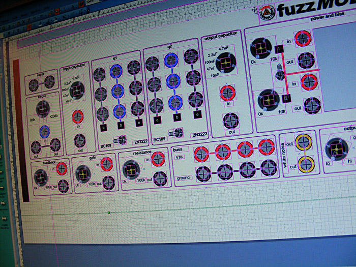
Design Time in Visio
The nice thing about Visio (besides the fact that I know it inside and out) is that it supports layers. So on a design like this, I can create a layer for the enclosure, another for the drill template, another to lay out the physical parts, one for wiring, and one for the label to print on the front. These layers can be turned on or off so a single drawing becomes a collection of printable templates for the entire design process.
For the enclosure, I chose a Hammond 1441-18. This is an aluminum enclosure most typically used for amplifier chassis work.
After the initial design, I printed out the Enclosure + Parts layers and taped them to the top of the enclosure to see if they would fit. This is a great time-saver because you can see exactly how the parts will line up in the enclosure before you do the drilling.
Parts Layout Check
Next it was off to the drill press. I taped a new printout (with the drilling template) to the box and drilled away. I used a nibbler to make the large cutout for the DC power meter.
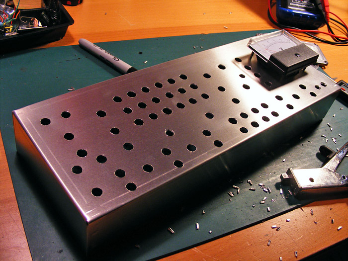
Drilling Done!
As with the Armageddon Processor, this is not going to be a pedal, but a table-top unit. So using my wood sides template, I cut out, sanded, stained and poly'd a couple of pieces of nice red oak. A few bolts on the sides and it is now fully upright.

Classy Sides there Tex!
When it came time to print out the label layer from Visio, I found that I was out of the trusty Office Depot brand glossy ink-jet sticker paper. But the iron was hot and I wasn't about to get in the car and go find some. I wanted this sucker done! After ferreting through my paper drawers, I came across some Office Depot Window Sticker paper. This is clear stuff that accepts ink jet printing pretty well. It is also adhesive on one side. I printed it off, aligned it, trimmed it, and stuck it on. It was a bit of work to get some of the bubbles out, but it turned our fairly nicely. Note that to get this stuff to look good, I had to power-sand (using 150 grit paper) the entire top of the enclosure. The sanding process got rid of the bumps, burrs and ridges caused by drilling all the holes.
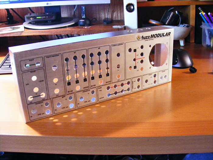
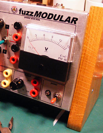
Label on, looking good!
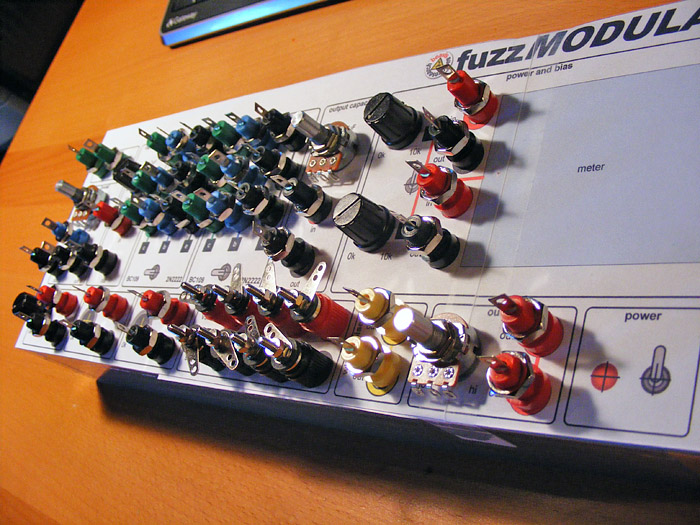
Next up: assembly. Is started with the meter and worked right to left. This is probably one of my favorite parts of any project--the mechanical assembly.
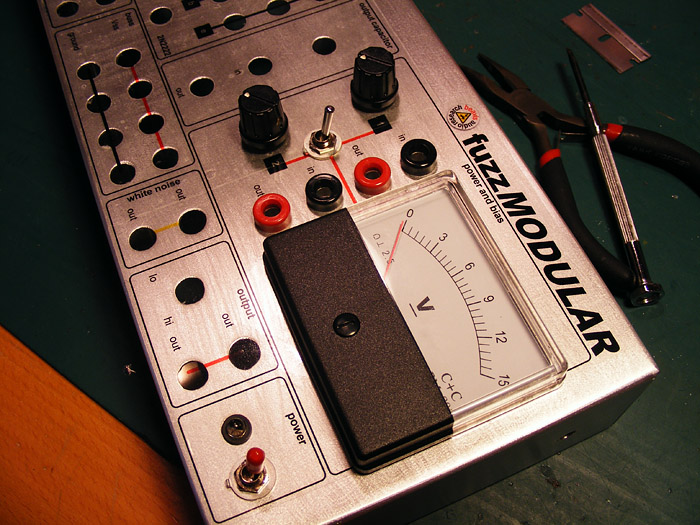
Parts Assembly
After a bunch more work, the assembly is done. Turned out pretty nice. Now on to the wiring!
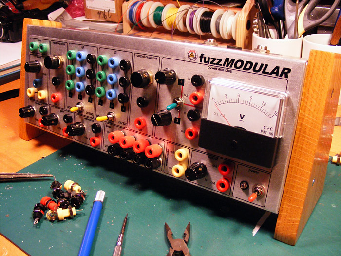
Assembly done!
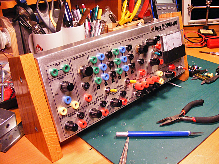
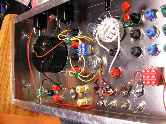
The wiring will take a bit of work. Here's where I am so far.
For the transistors, I wanted to switch between two different types for Q1 and Q2. The easy answer was is a pair of 3PDT switches. I glued rubber stoppers on each side of the switch and then glued inline sockets to the stoppers. You can see one of the switch assemblies, along with a nice selection of yummy vintage transistors here:
And here is a completed assembly installed in the enclosure, ready to be wired to the switches.
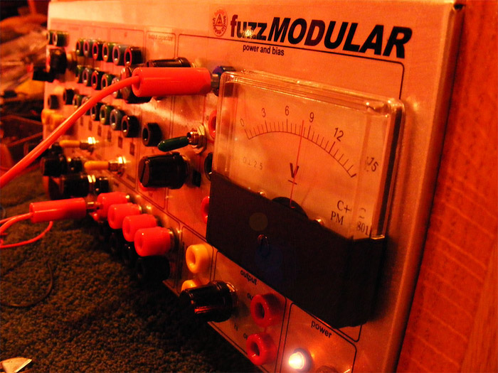
Power Testing:
more to come....
